Table of Contents
Ventilation Ducts within the insulation layer
A supporting tool for this topic is available in this guidelines and tools kit: Deep Renovation Guidelines Kit
Author: Jürgen Schnieders
Ventilation ducts under the exterior insulation
If old buildings are equipped with ventilation systems with heat recovery as part of a refur-bishment, it often offers advantages if the supply and extract air ducts can be installed out-side the home for the most part. Among other things, less work is required inside occupied flats in this case. One option is to lay the ducts on the outside of the existing external wall and then cover them with thermal insulation. With prefabricated insulation elements, it makes sense to install the ventilation ducts in the elements at the factory. The heat recovery unit can be located either outside the thermal envelope, e.g. in an uncon-ditioned attic, or inside the building / the flats. This type of installation results in additional transmission heat losses. It must also be taken into account that the air flowing in the ducts changes its temperature, which affects the ven-tilation losses. Based on a detailed analysis (see below) it was found that the following points must be considered.
Figure 1 shows a section through a ventilation duct which is installed in the thermal insulation on the masonry, as described. Three temperatures are involved in the resulting heat flows:
- the internal temperature Ti,
- the external temperature Ta,
- the temperature in the duct Tair.
As shown in the illustration, this situation can be modelled using a delta circuit of conduct-ance values H in W/(mK) between the temperatures mentioned above. Due to the linearity of the heat conduction equation, it is enough to determine the conductance values once using a 2D heat flow calculation for any temperature. In Figure 1 for example, Ti=Tair, heat flow over the internal surface is then H0(Ti-Ta), heat flow over the surface of the ventilation duct is Ha(Tair-Ta). For other temperature combinations, the heat flows can then be calculated using the same conductance values (superposition principle).
In the following calculations, it makes sense to use the difference to the regular heat flow instead of H0, i.e. ΔH_0=H_0-Ud(T_i-T_a ), where d is the length of the internal or external surface in the 2D model. ΔH_0 together with Hi and Ha then yields the additional heat flow due to the duct in the insulation level. In the analysed examples, H0 was always negative (typically approximately -0.04 W/(mK)), but the ventilation duct still leads to a slightly in-creased heat loss overall (typically approx. 0.01 W/(mK)) if the calculation is carried out via Hi and Ha.
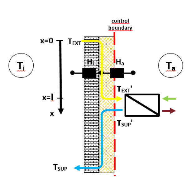
On this basis, a situation such as shown in Figure 2 can now be analysed in more detail. Different heat flows arise: the warm extract air with temperature TEXT=Ti in the thermal insulation generates increased heat loss via the external surface, but on the other hand it reduces the heat flow from the room into the wall. On its way to the ventilation unit, it gradually cools down so that air with the temperature TEXT' arrives at the connecting piece of the ventilation unit, colder than if the duct were routed inside the building. This shifts the temperature con-ditions in the ventilation unit itself and the supply air TSUP' is correspondingly colder. Depending on the heat recovery efficiency of the ventilation unit and the position of the duct, the supply air becomes warmer or colder on its way through the wall until it enters the room at the temperature TSUP.
In order to understand the influence of this situation on the transmission and ventilation losses of the building, it is helpful to precisely analyse the heat flows. On this basis, simplifica-tions can then be made for practical application.
First of all, it should be assumed that Tair has become stationary, as is the case e.g. with still air in the duct, but also at the end of a very long duct. The following will then apply:
This temperature will subsequently be referred to as the equilibrium temperature Teq The (two-dimensional) overall heat loss per metre of wall or duct length through the internal surface of the wall will then be
With reference to the external surface, the same value results in the form
The temperature of the air flowing inside the duct becomes similar to the equilibrium tem-perature exponentially. For instance, the following applies for the extract air duct
in which ![]() is the thermal capacity current in the ventilation duct.
At the connecting piece of the ventilation unit, after passing through the duct length l, the extract air still has the temperature
is the thermal capacity current in the ventilation duct.
At the connecting piece of the ventilation unit, after passing through the duct length l, the extract air still has the temperature
Also, at the connecting piece of the ventilation unit, the following supply air temperature is thus calculated by
where ![]() is the heat recovery efficiency of the ventilation unit on the supply air side.
is the heat recovery efficiency of the ventilation unit on the supply air side.
The supply air temperature on the inside can be determined in a way similar to that for the extract air temperature.
With the help of these interrelationships, it is now possible to determine the additional heat loss of the building caused by the ventilation ducts routed in the insulation. For calculating this correctly, it is essential to clearly specify the position of the balance boundary. In many respects, it proves to be particularly easy to specify this on the outer surface of the wall, in line with the conventions in the PHPP.

The losses in the area of the supply air duct can be determined in a similar manner. The ventilation losses result from the temperatures of the supply air and extract air flows through the building envelope.
The calculation procedure described here was implemented in a spreadsheet calculation and applied to some examples.


