Table of Contents
Façade Integration of Ventilation Units for Deep Renovation
A supporting tool for this topic is available in this guidelines and tools kit: Deep Renovation Guidelines Kit
Author: Rainer Pfluger
Facade Integration of Ventilation Unis – Options, Pros and Cons
If old buildings are equipped with ventilation systems with heat recovery as part of a refurbishment, it often offers advantages if this device are not placed inside the dwelling, but integrated in the façade. This way the device takes less space inside the dwelling and less work is required inside occupied flats in this case. Within outPHit a special tool for façade integration of units was elaborated, which will help you to quantify the heat transfer coefficient and the temperature factor fRSI depending on the mounting position of the unit.
Moreover, the maintenance of the device has to be considered. One option is from inside, but many housing associations are reluctant to choose this option when building rental apartments because appointments must then be made to enter the apartment for maintenance work. The other version is the maintenance from outside. However, a lift is required for this from the first floor onwards, if the unit is not accessible from a balcony or pergola. With regard to prefabrication, complete integration into the facade modules would be advantageous, but the device depth is then limited by the thickness of the facade. If the device requires a greater installation depth, either radiator niches or window openings can be used. When integrating windows, it may be possible to work with existing opening widths. The use of radiator niches, however, requires chiseling work.
Another option is to install it in a core hole drilled through the existing wall, either horizontally or inclined 45° downwards. This variant is also described below. Which of the variants is ultimately preferred must be decided on a case-by-case basis. The fundamental difference is that in the latter variant, the external air filter must be placed on the outside, and the duct distribution for supply and exhaust air is then carried out on the room side. When installing the appliance next to or under the window, on the other hand, this can also be done on the outside of the existing wall under the thermal insulation.
Ventilation Unit beside the window
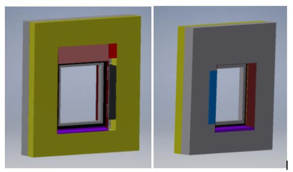
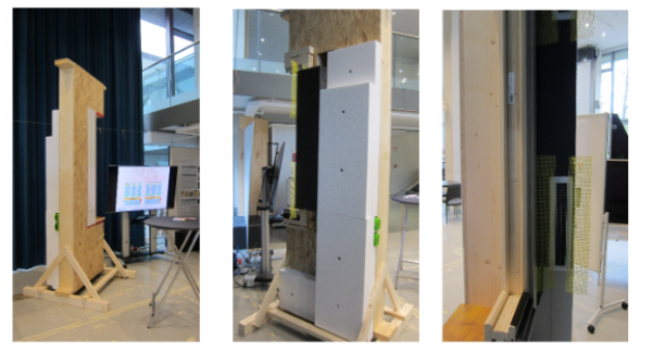
Provided that an EnerPHit renovation with correspondingly high insulation thicknesses and the replacement of the existing windows with highly efficient passive house windows is planned as part of the renovation, one option is to place the ventilation unit besides the window. In this case the size of the new window is smaller. If this is not acceptable, the position below the window (as it does not represent a load-bearing wall and can therefore be partially removed for horizontal installation without affecting the statics) or the mounting in a core hole drilling as described in the next chapter could be an alternative. Besides the heat recovery ventilation unit, all the required components can already be combined or pre-assembled in a prefabricated frame in the factory. But even during final assembly on the construction site, a mounting frame offers numerous advantages in terms of the quality of the connections. If a sun or privacy screen is installed above the window opening, there is no reduction in the free window opening; only one window per residential unit must be provided for the device width of 18 cm (or 20 cm including the soffit panel), which saves money and construction time. A living space should preferably be selected for device installation. The device has a switching flap through which the supply air can be directed either into the living room (during the day) or into the bedrooms (at night). This allows the total amount of air to be reduced because the air is specifically supplied to where the residents are. Alternatively, if the floor plan allows this, you can of course also work with extended cascade ventilation. Compared to the installation and air flow in new buildings (hoses in the system ceiling), during renovation, both the supply air and the exhaust air are now led outwards from the device into the insulation level at the top and bottom. A star distributor is installed there to branch to the supply and exhaust air rooms. In this way, all duct routes on the room side are eliminated, except for rooms that do not have an external wall (these must be connected in the classic way with ducts or supplied via active transfer valves.

A prototype of such an installaition was shown at the exhibition during the International Passivhouse Conference IPHC 2024 in Innsbruck.

Heat recovery in Core hole
As already mentioned, the approach presented in the previous section - the device in the existing shell opening - has the disadvantage of reducing the size of the window opening. All other solutions require additional new wall openings. In addition to the additional costs, noise and disruption, the admissibility in terms of statics must also be checked. A low-threshold form of external wall breakthrough is core hole drilling, which is relatively unproblematic and inexpensive to drill into brickwork or concrete using core drills. However, wall-integrated ventilation devices usually require rectangular openings with often considerable cross-sections and a correspondingly high level of construction effort. Therefore, a cylindrical countercurrent heat exchanger is proposed, which fits into a circular wall opening. Currently only cylindrical regenerative heat exchangers (push-pull fans) are available, but no cylindrical recuperative heat exchangers are available yet. However, such an arrangement is technically possible. If you want to utilize the circular cross-section as much as possible, different plate widths are required. Ideally, the cross section can be used almost completely. Classic recuperators have different plate shapes and geometries, which can be easily adapted to circular cross-sections. The following figure compares different variants and designs.
If you work with conventional plate heat exchangers, which for manufacturing reasons usually consist of stacks of plates with plates of the same area, you can only utilize a maximum of 63,7 % (edge length of the rectangle equals root of 2 multiplied by D/2) of the circular cross section of the core hole with a square cross section. The rest of the cross section should be filled with insulation.
If you divide the stack of plates into three packages (a central, wider rectangular cross-section and two identical, narrower cross-sections), you can access around 78.7% of the circular cross-section. This maximum area utilization ration is reached, if the ratio of the width of the large rectangle to the width of the small rectangle is the golden ratio (1 plus the root of five divided by two). The formulas for these dimensions are found to be
In many cases, a standard counter flow heat exchanger is made of a pile of plates, the number of plates pairs are variable and can be ordered by the manufacturer as desired. For the best use of space, the dimensions should be chosen as close as possible to those given by the formulas. The length of the heat exchanger is fixed and consists of the length of the rectangular middle part (countercurrent heat exchanger) and two triangles on its narrow side (usually rectangular). The total length L fitting in the wall with width B in case of a 45° inclined bore hole is
A prototype of a combination of three heat exchangers in combination was built accordingly as shown in the following pictures
For economic reasons, the square version might be the best option, as only one heat exchanger is necessary in this case. However – depending on the necessary flow rate – the heat exchanger and consequently the diameter of the core hole can become quite large. Whether core hole drilling of the respective diameter is permissible for static reasons must be checked on a case-by-case basis.
Summary
Within the outPHit project, several options for façade integrated ventilation systems were investigated and demonstrated by various prototypes. A checklist and a tool will help for planning and quality assurance. When planning a renovation, the first thing to decide is where the device can be installed as easily as possible. In addition, the question of whether the outdoor- and exhaust air ducts should be routed outside or inside must be clarified. According to this, the device position next to the window is to be preferred in the context of a complete renovation with ETICS and window replacement, and installation can be simplified and accelerated with the help of prefabricated installation frames. The option of a heat exchanger in the core hole, on the other hand, remains a solution if the ventilation is to be installed after the renovation of the building envelope.
References
[outPHit WPx ] Rainer Pfluger: Multifunctional window element in serial renovation, Innsbruck, 2024
[outPHit D4.6] Rainer Pfluger: Façade Integration of Devices, 2024 as part of Steiger, J.: outPHit D4.6 Deep Renovation Guidelines, 2024.
[outPHit Tool D4.6] Pfluger, R., Hammes, S.: Devices in the insulation layer, calculation Tool, v1.0, 2024.


