Table of Contents
Exterior wall on floor slab
A typical connection detail is shown below:
Note! Before preparing the calculation model, it should be checked which building component layers are relevant for the calculations and which can be disregarded. Thus for example, blinding layers can be disregarded which do not have any significant insulating effect on account of their material or due to their water permeability. It should also be considered whether poorer rated values apply for perimeter insulation which is outside of the moisture barrier or sealing layers.
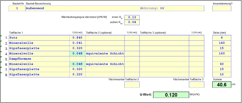
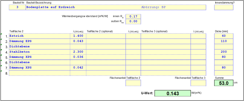
For the example given here, the bottom concrete layer (layer number 19) is disregarded because the insulating effect is small compared to the surrounding earth. The perimeter insulation (layer number 18) lies outside of the moisture barrier (layer number 17) and therefore has a poorer rated value for thermal conductivity according to the approval. The following U-value results for the exterior wall:
Calculation model
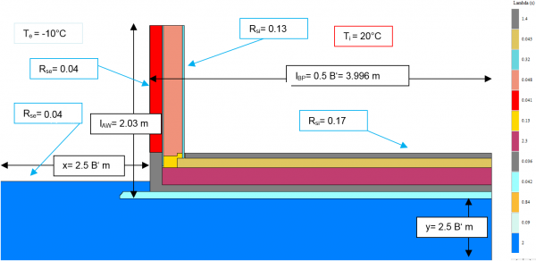
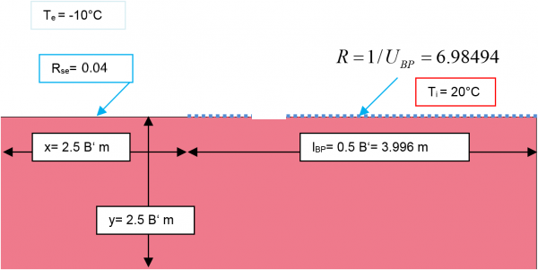
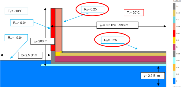
First, an overall model is prepared for calculating the conductance $L_{2d}$. If the actual size of the building is not known, B‘ can be selected for the option B, but it should not be too small ($B' > 5 \, \text{m}$). $B' = 7{,}992 \, \text{m}$ was selected here (including the exterior wall) [Note: With some heat flow software programs the dimensions in the models may have inconvenient decimal places; however this is not of any significance]. The floor slab is only modelled up to the axis of symmetry and thus has the length $\frac{B'}{2}=3{,}996 \, \text{m}$. The height of the exterior wall should be three times as high as the area to be examined. It is essential that the length is measured based on the exterior references, that is, up to the lower edge of the perimeter insulation. The same dimensional reference should be used in the respective PHPP calculation. In the example shown here, the length of the exterior wall is 2.03 m. The block of earth should be modelled with a size of at least $2{,}5 \cdot B'$. In the following illustration all relevant reference dimensions and boundary conditions are included. Ultimately, it is irrelevant which boundary conditions for the temperature are used for determining the conductances; however, it is recommended that those should be used which will be needed later on for determining the surface temperatures. The lower part of the illustration shows the calculation of the conductance $L_{2d}$, this results from the heat flow calculated using the heat flow software program.
Calculating the conductance $L_{2d}$
$$ \dot{q} = 19{,}488 \, \frac{\text{W}}{\text{m}} $$
$$ \large{L_{2d} = \frac{\dot{q}}{T_i-T_e} = \frac{19{,}488}{30} = 0{,}6496 \, \frac{\text{W}}{\text{m} \cdot \text{K}}} $$
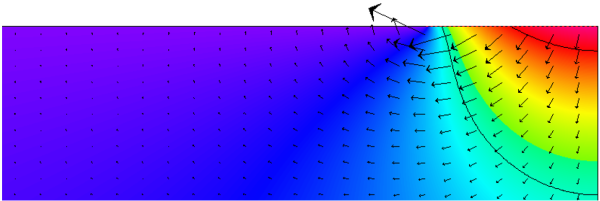
In the next step, the conductance of the floor slab must be determined. According to option B in the standard, as mentioned before this takes place through an additional simulation. In DIN EN ISO 10211 the exterior wall is removed for this purpose and substituted with an adiabatic boundary. It is better to take the floor slab into account in the calculation only with its transfer resistance. For this, the transfer resistance is displayed with the corresponding length (in this example with $l_{BP}=3{,}996 \, \text{m}$) on the given block of earth. Because the norm DIN EN ISO 13370 as well as the PHPP assume that floor slabs are laid on the ground, this transfer resistance is level with the ground surface although the floor slab reaches a few centimetres into the ground. This has the effect that the resultant Ψ-value matches the assigned basic assumptions in the calculation approach of the PHPP.
Conductance of the floor slab $L_{BP}$
$$ \dot{q} = 14{,}023 \, \frac{\text{W}}{\text{m}} $$
$$ \large{L_{BP} = \frac{\dot{q}}{T_i-T_e} = \frac{14{,}023}{30} = 0{,}4674 \, \frac{\text{W}}{\text{m} \cdot \text{K}}} $$
The conductance of the exterior wall will now be determined, after which the Ψ-value of the whole connection can be calculated as shown below:
Conductance of the exterior wall $L_{AW}$
$$ U_{AW} = 0{,}1205 \, \frac{\text{W}}{\text{m}^2 \cdot \text{K}} $$
$$ \large{L_{AW} = l_{AW} \cdot U_{AW} = 2{,}03 \cdot 0{,}1205 = 0{,}2446 \, \frac{\text{W}}{\text{m} \cdot \text{K}}} $$
Calculation of the Ψ-value
$$ \large{\Psi = L_{2d}-L_{AW}-L_{BP}=0{,}6496-0{,}2446-0{,}4674=-0{,}062 \, \frac{\text{W}}{\text{m} \cdot \text{K}}} $$
In practice, pre-prepared Excel templates for calculating the Ψ-values should be used for simplification. One can enter the heat flows and the necessary lengths here and the desired Ψ-value is received as the result directly.
Note regarding the result! The relatively strongly negative Ψ-value is due among other things to the fact that the existing insulation skirt is also depicted in the Ψ-value. The person processing this information should be aware that the Ψ-value shown here contains not only the geometric thermal bridge effect in the classic sense but also includes other effects besides the insulation skirt. Thus, in this example the Ψ-value also takes into account the fact that the floor slab is slightly sunk into the ground and therefore a small part of the exterior wall also lies in the ground.
Attention ! If the connection to be calculated has an insulation skirt, then its influence will also be depicted in the Ψ-value. In the PHPP the edge insulation therefore must not be entered additionally as it would then be taken into account twice.
Determining the surface temperature
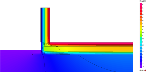
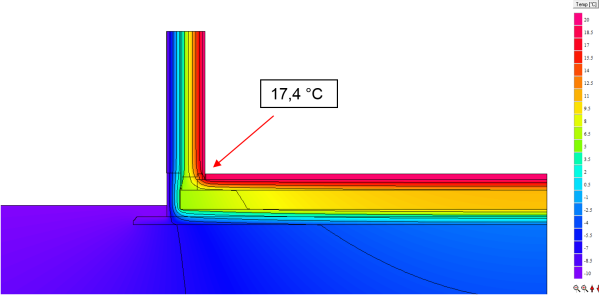
For determining the minimum surface temperature and the $f_{Rsi}$ factor, the same procedure as for any other thermal bridge can be used in this case as well.
Determining the minimum surface temperature and $f_{Rsi}$
$$ f_{Rsi \, = \, 0{,}25} = \frac{17{,}4-(-10)}{20-(-10)} = 0{,}91 $$


