This is an old revision of the document!
Table of Contents
Step-by-step retrofit: Airtightness concept
Author: Soeren Peper
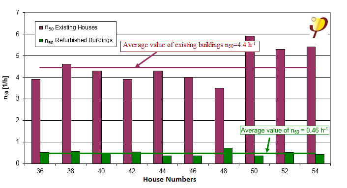
For a step-by-step retrofit, a concept for airtightness should be developed right at the start of the measure. For each refurbishment step, it must be clarified whether airtightness is affected and how this can be improved. If this is not done, individual steps may have a significant negative impact on airtightness. Due to individual construction measures, circumstances may be created which cannot be reversed with justifiable effort later on. As a consequence, airtightness of the building can remain permanently set at a moderate level. For this reason, airtightness should form an element of the concept for all partial steps right from the start of the step-by-step modernisation. For assessing the initial situation, an airtightness measurement in advance is recommended. This applies especially for larger modernisation projects. The main leakages can be identified in the process and these findings can then be taken into account in the concept development. Further intermediate measurements are recommended if there is a large time interval (several years) between planned modernisation steps. Although this represents a certain amount of extra effort, it may provide important insights relating to the success of the previous step and for the measures of the following steps. For the Tevesstrasse project in Frankfurt am Main (multi-storey building with a total of 53 apartments), which was refurbished using Passive House components, a comparison of the airtightness values measured before and after the modernisation measures demonstrated the effectiveness of the concept developed at an early stage and its successful implementation. Comparison of the airtightness values in Figure 1 shows an improvement by a factor of 10: the average value of 4.4 has been reduced to 0.46 h-1. This illustrates the huge progress made in the area of the airtight envelope in these buildings. In this refurbishment, besides the systematic improvement of the building envelope, this was in part due to the fact that there were no longer any air vents in the kitchens, which have previously been used for supplying air to the coal burning stoves.
The importance of developing a concept for airtightness at an early stage of step-by-step modernisation will be explained here using an example.
Case study: Modernisation of a detached house in Zellingen
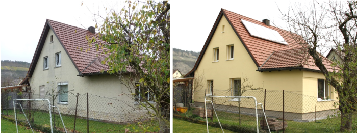
The detached house in Zellingen near Würzburg (Bavaria) was built in 1959. The size of the heated living area is 126 m². The first modernisation step took place in 1999 with extensive refurbishment of the roof, window replacement, and renovation of the bathrooms and flooring. Among other things, insulation on rafters was implemented using aluminium-coated insulation panels and the roof covering was renewed. The original windows were replaced with double glazed PVC windows. The next step of the modernisation was carried out in 2014 with extensive insulation of the building (EIFS) and the installation of a solar thermal system and a ventilation system with heat recovery. The third step of the modernisation will take place in the next few years with the substitution of the windows with products of a high thermal quality. The renewal of the windows has already been taken into account currently by affixing a wooden construction around the windows, into which the new windows will be mounted in the centre of the insulation layer in an optimal way without damaging the thermal insulation.
The roof area of the building was timber-cladded on the inside. This was also the reason why the decision for insulation on the roof was made for the roof renewal in 1999. This measure could be carried out completely from the outside without any problems. A concept for airtightness was not developed at the time, and the subject of airtightness was not considered any further. The aluminium-coated insulation panels were laid using a tongue-and-groove system without any other airtight sealing between these. Since airtightness was not tested after the installation, the issue of the lack of sealing could not be addressed.
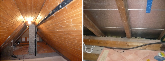
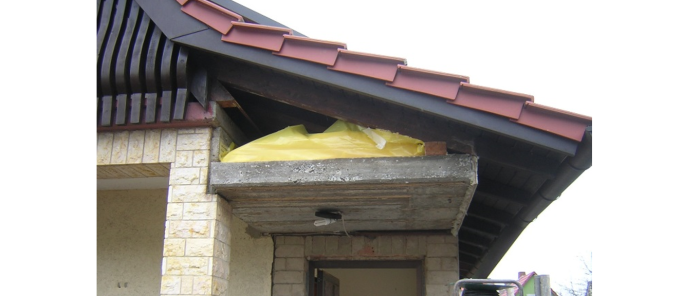
The subject of airtightness became relevant with the next modernisation step in the year 2014. No changes were planned for the already renewed roof. In order to improve airtightness of the roof space, the timber cladding of the roof area was almost entirely removed on the inside. The aluminium-coated insulation panels served as the airtight layer. An attempt was made to seal the joints between the panels using adhesive tape and a sprayed-on compound. However, sealing could not be implemented at the regularly-occurring points where the insulation panels rested on the rafters because the panels could not be raised. All these points represented leaks. The attempt to seal the panels all around alongside the rafters (on both sides) significantly extends the sealing surface by several times. In addition, the problem was shifted from the annexe and entrance area to the inaccessible connection points at the eaves, partly at the roof ridge and the junction of the main roof with the roof of the entrance porch. The leakage area could be reduced through work involving a lot of time and resources, but permanent and adequate airtightness could not really be achieved in this way. The following figures show the leaks and the extremely complicated efforts made for sealing, which were only partially successful.
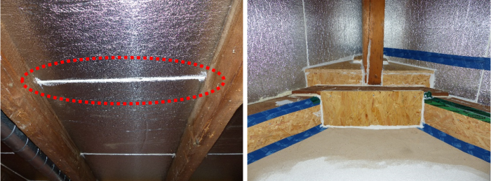
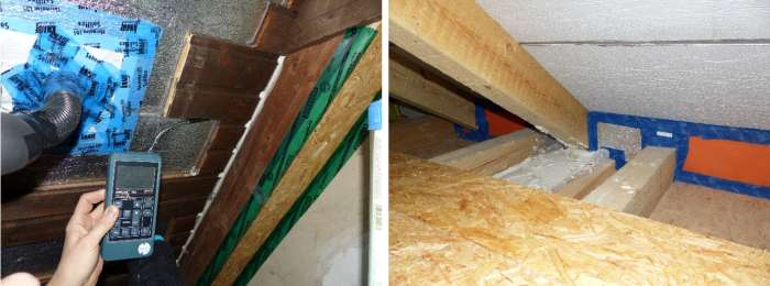
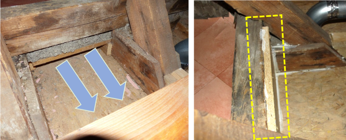
Double floors with openings towards the attic existed in some attic areas. At negative pressure, massive air flows passed through these openings into the attic. The point of entry on the outside was inaccessible or could not be ascertained. Supposedly this was the edge of the aluminium covered insulating panels at the eaves. As an effort was made to seal this tapered area at the transition of the attic floor to the roof from inside the roof area using boards etc. (Figure 5 / right), there was now increased air flow through this empty space. After this fault had been localised, an attempt was made to seal this leak using boards here as well (Figure 6). However, this was not completely possible on account of the interruption of the leakage surface due to the roof rafters.
Had a concept for airtightness been developed at an early stage, the focus would have had to be on the sealing of the roof area together with the connections to the airtight layer of the lower part of the building (existing exterior plaster). Various solutions would have been considered; a concept with the least possible penetrations should always be selected. In general, it is challenging when the airtight layers of different areas cannot simply be directly joined with each other. The connection of the roof area to the airtight layer of the walls of the room below – as in the present example - is typical. In such cases, good airtightness values often cannot be expected. The schematic diagrams in Figure 7 show which of the two systematic solutions are conceivable for this in the case of a refurbishment involving wood beam ceilings. One possibility is the airtight connection “through” or “in front of” the wood beam ceiling (around the outside). For this, the sheeting can be passed directly through between the beam heads, but it must be carefully sealed around each beam. This presupposes accessibility of the entire area. The possibility shown in the figure is to airtightly “wrap” the entire ceiling space all around (in this cross-section, e.g. up to the opening for the stairs or trapdoor). This should only be implemented if sufficient wind-tightness of these areas is ensured on the outside, otherwise cold air may pass through these “facade constrictions” with large surface areas and the heat losses of the building could increase noticeably.
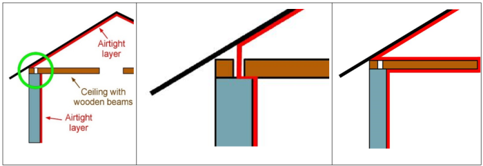
A third solution that is possible is to shift the airtight layer to the outside of the building. This can be done by inspecting and reinforcing of the old plaster if necessary, or by applying filler. However, this only makes sense if thermal insulation is applied afterwards as soon as possible, in order to protect this layer permanently from thermal stresses (formation of cracks). This airtight layer on the old exterior surface must then be consistently connected at all relevant points (base point of the building and roof to attic transition).
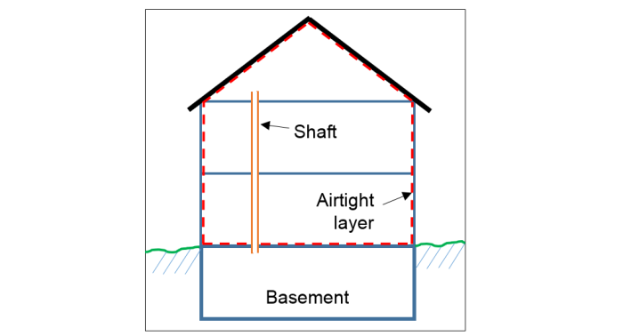
Shaft connecting the basement and attic floor
In the building there was an installation shaft which connected the basement with the attic floor (see Figure 8). Cables passed through this shaft and since the modernisation, also the supply lines for the solar heating system. Because the basement was situated outside of the airtight envelope, the shaft represented a potential leakage therefore it had to be sealed airtightly.
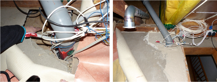
In practice, this was not easy to do because of restricted accessibility and the different materials etc. Pouring with thin plaster or expanding mortar proved to be a good solution (Figure 9). Before using this, the shaft had to be stuffed with construction foam so that the plaster or mortar did not drain away downwards, and a plug was formed. All cavities and spaces as well as the areas between cables and wires are filled completely due to the thinness of the plaster.
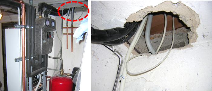
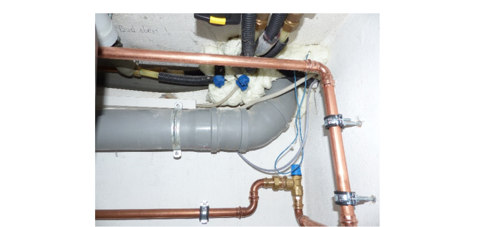
In another area of the basement, there was a second shaft end with more lines towards the first floor (Figure 11). The same situation existed here with reference to airtightness. When preparing the concept for airtightness, such areas should be identified early on and taken into account in the concept. Defined starting and ending points, and specification of a method for sealing will facilitate the procedure. In this way there will be no surprises during the airtightness measurement due to this leak.
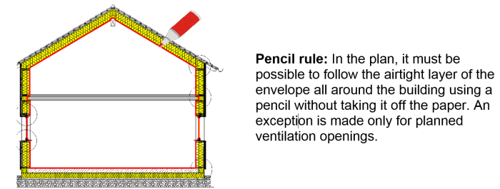
A typical problem arising during modernisation is the lack of clarity regarding the course of the airtight layer. In a rough concept the “pencil rule” principle must be applied, in which the uninterrupted airtight layer is clearly specified by the architect in all cross sections (Figure 12). In the ensuing detailed planning, detailed solutions with information about the materials used must be prepared for all transitions and connections. Only in this way will it be possible to ensure that solutions exist and that craftpersons are given clear instructions for executing the work.
Airtightness measurements
In the example building in Zellingen, a separate concept for airtightness was not prepared for the first step of modernisation (1999), and the level of airtightness was not tested after the implementation of the measures. For the second step of the modernisation (2014), three airtightness measurements were carried out in total. The first measurement was carried out for testing the sealing work. This revealed that massive leakages existed and some points had not been sealed or were inadequately sealed, or had been sealed at the wrong places. The main point of leakage was localised above the entrance area at the transition to the roof.
Due to the low airtightness of the building during the first Blower Door measurement (n50 = 8.9 h-1), further sealing work was carried out and an attempt was made to seal the large leak in the area of the roof connection in particular. The complicated sealing work was tested during the second measurement which took place two weeks later. It turned out that numerous leaks still existed despite significant improvements. The measured value was reduced by almost a half. In particular, the leaks discussed previously were identified as the biggest source of leakage:
- insulation on rafters which consisted of unsealed panels, including lack of seals between wall & roof insulation layers along the eaves and verges
- inadequately sealed channels towards the basement
- double floors in the attic space
In order to finally check the improvements due to the sealing of these leaks, a third Blower Door test was carried out for this building seven weeks later. Again, the sealing work took a lot of time and effort. The leakage volume flow at 50 Pa was reduced by a further 480 m³/h. A n50 value of 3.6 h-1 was thus achieved. For an energy efficient building with a ventilation system, this value was significantly higher than the desired value, despite all the efforts and improvements achieved. Other notable subsequent improvements were no longer possible with justifiable effort in terms of time and costs.
| Date | n50 -Value [1/h] | |
| Meassurement 1 | 24.01.2014 | 8,9 |
| Meassurement 2 | 07.02.2014 | 4,8 |
| Meassurement 3 | 31.03.2014 | 3,6 |
Table 1: Measured values of the three airtightness measurements performed for the building in Zellingen
Recommendations for the airtightness concept
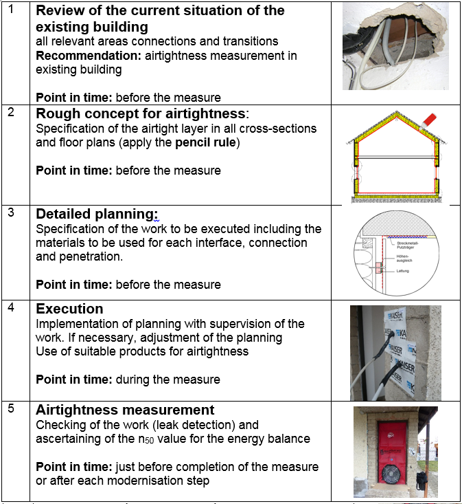
Using this example case and the results of the airtightness measurements and leak detection, the need for a comprehensive concept for airtightness is clearly evident. This must be prepared at the start, before any of the modernisation measures. For this, it is necessary to have a detailed record of the current state of all relevant points, and the exact position of the airtight layer must then be specified in the concept (sketch). Finally a solution must be developed for all connections and transitions, using a detail drawing if necessary, and the materials to be used for these points and connections must be specified.
Literature
| [Feist/Peper 2005] | Feist, W; Peper, S.: 3-D-Luftdichte Anschlüsse. (3-D Airtight Connections) Passive House Institute, Darmstadt, 2005. Not published. |
| [Kaufmann et al. 2009] | Berthold Kaufmann; Søren Peper; Rainer Pfluger; Wolfgang Feist: Sanierung mit Passivhaus-Komponenten, Planungsbegleitende Beratung und Qualitätssicherung Tevesstraße Frankfurt a.M., Bericht im Auftrag des Hessischen Ministeriums für Wirtschaft, Verkehr und Landesentwicklung, Wiesbaden, Passivhaus Institut, Darmstadt, 2009. Download unter: www.passiv.de Refurbishment using Passive House components, consultation during planning and quality assurance for the Tevesstrasse Project in Frankfurt, Report commissioned by the Ministry of Economy, Transport and Regional Development of the German State of Hessen, Wiesbaden, Passive house Institute, Darmstadt 2009 |
| [Peper/Feist/Sariri 1999] | Peper, S., Feist, W.: Luftdichte Projektierung von Passivhäusern, CEPHEUS-Projektinformation Nr. 7, Passivhaus Institut, Darmstadt, 1999; Fachinformation PHI-1999/6, 10. Auflage Oktober 2009. Airtight planning of Passive Houses, CEPHEUS Project Information No. 7, Passive House Institute, Darmstadt 1999; Technical Information PHI-1999/6, 10th edition, October 2009 |
| The sole responsibility for the content of Passipedia lies with the authors. While certain marked articles have been created with the support of the EU, they do not necessarily reflect the opinion of the European Union; Neither the EACI nor the European Commission are responsible for any use that may be made of the information contained therein. |


