Table of Contents
Unheated basement
Basic principles
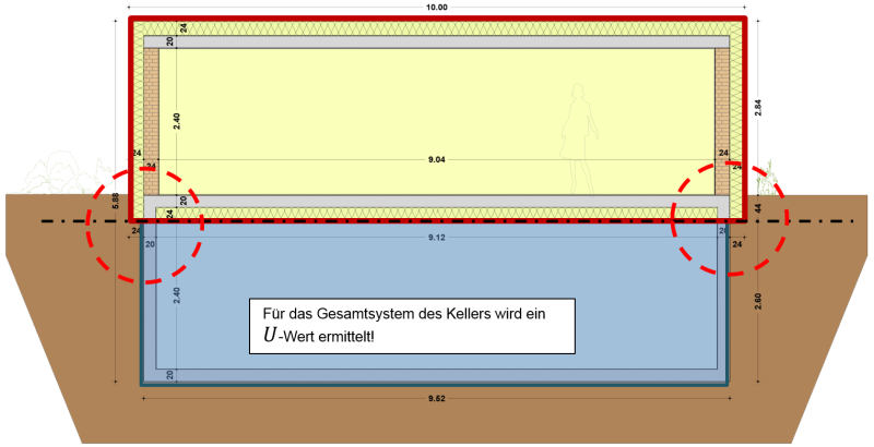
Active temperature control does not take place in unheated basements. As a rule, lower temperatures prevail in these, therefore thermal separation of the basement from the heated part of the building is necessary. In energy balances the unheated basement is not taken into account in the treated floor area, but it does represent an additional heat transfer resistance between the heated interior space and the outdoor air which has to be taken into account.
This transfer resistance is assigned to the boundary surface between the basement and the interior space (see figure above). This is expressed by the following U-value:
$$
\large{\dfrac{1}{U} = \dfrac{1}{U_f} + \dfrac{A}{(A \cdot U_{bf}) + (z \cdot P \cdot U_{bw}) + (h \cdot P \cdot U_W) + (0{,}33 \cdot n \cdot V)}}
$$
Equation 1 based on DIN EN ISO 13370, Section 9.4
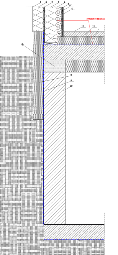
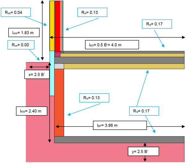
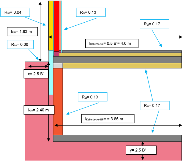
$U_f$ is the heat transfer resistance of the basement ceiling. $U_{bf}$ and $U_{bw}$ are the U-values of the basement floor slab and the basement wall respectively and are based in turn on the approximation function of the norm for taking into account of the ground. Ventilation of the basement is also taken into account. In order to allow energy-relevant evaluation of the connection situation between the basement and the interior space, another Ψ-value must be calculated for the energy balance. Several methods exist for this purpose which are demonstrated on the basis of the following detail:
Normative method
Calculation of the conductance
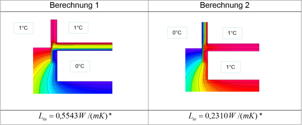
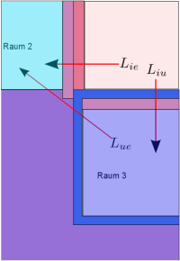 For the unheated basement, the overall value $L_{2d}$ must also be calculated as it is for the floor slab and the heated basement. The required heat flow from the heated space consists of the conductances $L_{ie}$ and $L_{iu}$:
$$ \large{\Phi = L_{iu} \cdot (\theta_i - \theta_u) + L_{ie} \cdot (\theta_i - \theta_e)} $$
However, the indoor temperature $\theta_u$ of the basement is unknown, therefore $L_{2d}$ cannot be calculated directly, but with the use of $L_{ue}$ it is possible to express the heat flow or the conductance using the following equation:
$$ \large{\Phi = \left(\frac{L_{iu} \cdot L_{ue}}{L_{iu} + L_{ue}}\right) \cdot (\theta_i - \theta_e) \quad \Rightarrow \quad L_{2d} = \left(\frac{L_{iu} \cdot L_{ue}}{L_{iu} + L_{ue}} + L_{ie}\right)} $$
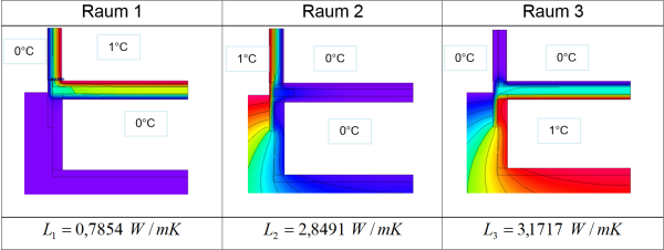
Thus $L_{ie}$ , $L_{iu}$ and $L_{ue}$ need to be determined. For this purpose, first the conductances of the separate partial areas are ascertained and the following system of equations is solved:
$$ \begin{matrix} & \begin{matrix}L_{iu}&L_{ie}&L_{ue}\end{matrix} \\\\ \begin{matrix}L_1\\\\L_2\\\\L_3\end{matrix} & \begin{pmatrix}1\quad&1\quad&0\quad\\\\0\quad&1\quad&1\quad\\\\1\quad&0\quad&1\quad\end{pmatrix}\\\\ \end{matrix} \quad \Rightarrow \quad \begin{matrix} L_{iu} = 0{,}5 \cdot (L_1-L_2+L_3) \\ L_{ie} = 0{,}5 \cdot (L_1+L_2-L_3) \\ L_{ue} = 0{,}5 \cdot (-L_1+L_2+L_3) \end{matrix} $$
In order to be able to read the conductances of the individual areas directly from the heat flow program, it makes sense to choose the temperatures so that the temperature difference to the respective neighbouring rooms amounts to one Kelvin. These calculations are demonstrated using an example:
Determining the conductance $$ \Large{_{2d}} $$
$$ \large{ L_{iu} = 0{.}5 \cdot (L_1-L_2+L_3) = 0{.}5540 \, \frac{\text{W}}{\text{m} \cdot \text{K}} \\ L_{is} = 0{.}5 \cdot (L_1+L_2-L_3) = 0{.}2314 \, \frac{\text{W}}{\text{m} \cdot \text{K}} \\ L_{us} = 0{.}5 \cdot (-L_1+L_2+L_3) = 2{.}6177 \, \frac{\text{W}}{\text{m} \cdot \text{K}}} $$
$$ \large{L_{2d} = \left(\frac{L_{iu} \cdot L_{ue}}{L_{iu} + L_{ue}} + L_{ie}\right) = 0{.}6886 \, \frac{\text{W}}{\text{m} \cdot \text{K}}} $$
Calculating the Ψ-value
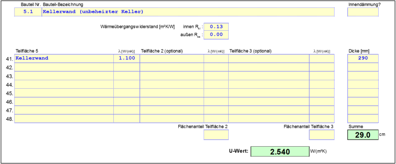
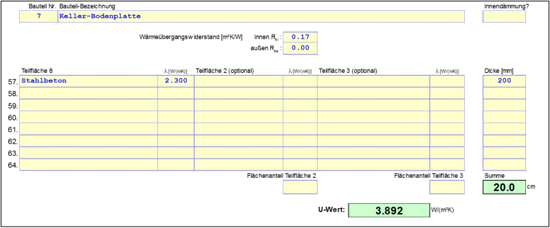
The substitute U-value of the basement level is calculated in accordance with Equation 1. Because the heat losses due to the ventilation of the space are not taken into account when determining the conductance, these may not be included in the U-value either.
Therefore:
$$ \dfrac{1}{U} = \dfrac{1}{U_f} + \dfrac{A}{(A \cdot U_{bf}) + (z \cdot P \cdot U_{bw}) + (h \cdot P \cdot U_W) + (0{.}33 \cdot n \cdot V)} \quad \Rightarrow \quad U = 0{.}1273 \, \dfrac{\text{W}}{\text{m}^2 \cdot \text{K}} $$
When entering the key data, this value can be taken from the Ground worksheet of the PHPP; for this, some rows in the Ground worksheet must be displayed first. Calculation of the Ψ-value now takes place in accordance with DIN EN ISO 10211 by means of the following formula:
$$\Psi_g = L_{2d}-l_{AW} \cdot U_{AW}-0{.}5 \cdot B' \cdot U$$
Calculation of the Ψ-value
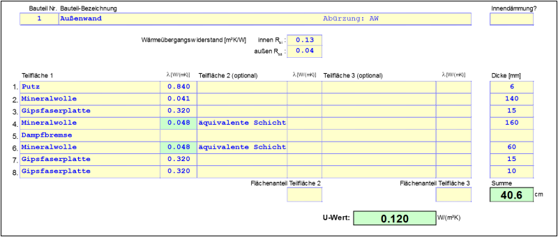
$$\Psi_g = 0{.}689 \, \dfrac{\text{W}}{\text{m} \cdot \text{K}} \, - \, 1{.}830 \, \text{m} \, \cdot \, 0{.}120 \, \dfrac{\text{W}}{\text{m}^2 \cdot \text{K}} \, - \, 0{.}5 \, \cdot \, 8 \, \text{m} \, \cdot \, 0{.}1273 \, \dfrac{\text{W}}{\text{m}^2 \cdot \text{K}} = -0{.}042 \, \dfrac{\text{W}}{\text{m} \cdot \text{K}}$$
With this procedure, it is assumed that the Base Area A of the basement level based on exterior dimensions correlates with the boundary surface of the ceiling area, which usually is not true, of course. The difference to the reality is thus also depicted by the U-value among other things.
Procedure according to Protocol Volume Number 27
Determining the conductance
An alternative procedure is given in the Protocol Volume No. 27 of the Research Group for Cost-effective Passive Houses and is demonstrated below. Only the conductances $L_{ie}$ and $L_{iu}$ are required for this method. These can be determined through two calculations.
Determining the conductance $ \Large{L_{2d}} $
* For a temperature difference of 1 K the conductance has the same numerical value as the sum of the heat flows across all interior surfaces of the interior space.
Note! In comparison to the previous variant, $L_{ie}$ and $L_{iu}$ were calculated with only 2 simulations here. In this case the desired heat flows must be determined as part of the overall heat flux in the model, which is relatively confusing or even impossible depending on the software used. Alternatively, the conductances can be ascertained as in the previous variant, but again with the aid of three simulations.
Calculating the Ψ-value
The conductance $L_{iu}$ is now assigned to the floor slab, $L_{ie}$ is assigned to the exterior wall. The effect of this thermal bridge is therefore expressed by two Ψ-values. The following applies for the exterior wall:
Ψ-value (proportion of exterior wall)
$$ \large{\Psi_g = L_{ie}-l_{AW} \cdot U_{AW}} $$
$$ \large{\Psi_{exterior wall} = 0{.}231-1{.}830 \cdot 0{.}120 = 0{.}0114} $$
For the floor slab:
Ψ-value (proportion of floor slab)
$$ \large{\Psi_g = L_{iu}-0{.}5 \cdot B' \cdot U_{basement ceiling}} $$
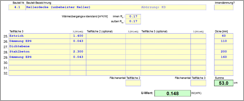
$$ \large{\Psi_{basement ceiling} = 0{.}5543-0{.}5 \cdot 8 \cdot 0{.}148 = -0{.}0377} $$
In the PHPP $\Psi_{exterior wall}$ is entered as a normal thermal bridge. With $\Psi_{basement ceiling}$, $U_f$ for the basement ceiling is corrected in the Ground worksheet so that the overall resistance of the basement level can be calculated afterwards with the aid of the approximation functions.
$$ \large{U_{f,corrected} = U_f + \dfrac{\Psi_{basement ceiling} \cdot P}{A}} $$
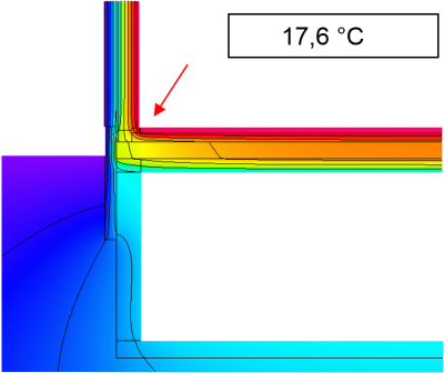
Determining the minimum surface temperature and the f_Rsi factor
Generally, evaluation of the minimum surface temperatures and determination of the $f_{Rsi}$ factor based on steady-state calculations for building components in contact with the ground is reliable only to a certain extent because heat storage and phase shifts in the ground are not considered. In addition, in the context of certification of a building component, the size of the basement later on is not known. For these reasons, it is very difficult to draw any conclusions about the temperatures that occur in unheated basement areas. The PHI recommends the following procedure for steady-state calculations:
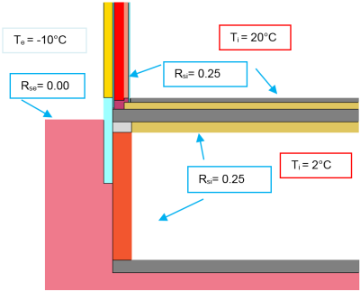
In order to calculate the temperature of the unheated basement, a temperature correction factor of $f_x=0{.}6$ is used. This gives the following basement temperature:
$$ \large{\theta_{basement} = \theta_i-f_x \cdot (\theta_i - \theta_e) = 20 \, ^\circ C - 0{.}6 \cdot (20 \, ^\circ C - (-10 \, ^\circ C)) = 2 \, ^\circ C} $$
These $2 \, ^\circ C$ are then used as a boundary condition for the temperature in the basement. On account of cabinets and other large items, the higher heat transfer resistance $R_{si} = 0{.}25 \, \frac{\text{m}^2\cdot \text{K}}{\text{W}}$ should be used here as well.
Determining the minimum surface temperature and $$ \Large{f_{Rsi}} $$
$$ \large{f_{Rsi} = \dfrac{17{.}6 - (-10)}{20-(-10)}=0{.}92} $$
Information! The $f_{Rsi}$ factor for thermal bridges with three boundary conditions for the temperature is not defined in the norms. The norm DIN EN ISO 10211 requires temperature correction factors to be stated with which it is possible to ascertain the minimum surface temperature for any combination of indoor temperatures. However, in this case the basement temperature is linked via $f_x$ to $\theta_i = 20 \, ^\circ C$ and $\theta_e = -10 \, ^\circ C$, so a $f_{Rsi}$* factor can also be given here.

