This is an old revision of the document!
Table of Contents
Basic principle for calculating thermal bridges
For calculating thermal bridges, it is first necessary to model the corresponding building component connections for a heat flow program. The individual thermal conductivities of the materials must also be given besides the geometry. Furthermore, boundary conditions for temperatures and heat transfer resistances should be selected. The norm DIN EN ISO 10211 is decisive for the calculation of thermal bridges in building engineering. The calculations of the $\Psi$-value and determination of the minimal interior surface temperature can be performed using the same model, but other boundary conditions should be selected in each case, as described below.
Determining the thermal transmittance
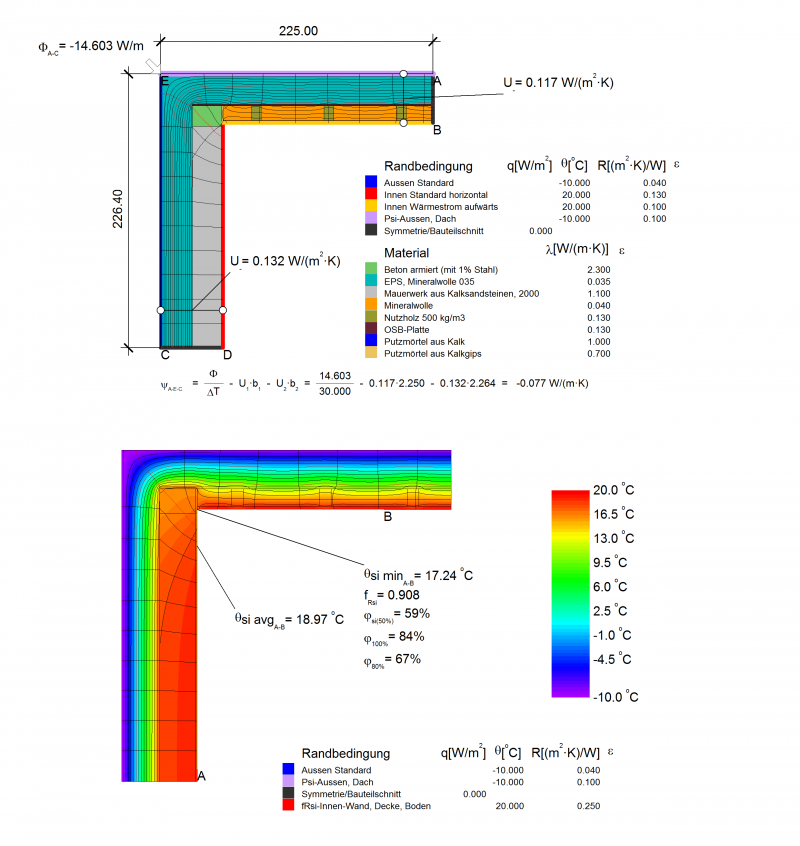
The principle for calculating the linear thermal transmittance is depicted in the illustration below. The $\Psi$-value represents the difference between the thermally interrupted component and the uninterrupted component that is assumed for the balance. First the heat flow or the conductance $L_{2d}$ is determined by means of the heat flow simulation. To determine the $\Psi$-value, $L_{0}$ is deducted from the conductance of the uninterrupted building component. It is essential that the linear reference is adhered to all throughout. If interior references are used in the context of energy balancing, then $\Psi$-values based on interior references must also be used. However, exterior dimensions are used more often in practice as these can easily be taken from plans and measurements. Exterior dimensions are therefore consistently used in the PHPP.

Boundary conditions/ transfer resistances
Because the conductances are independent of the assumed boundary conditions for the temperatures, it does not matter which temperatures are set for the inside and outside as long as there is a temperature decline due to the building component. In practical terms, the same temperatures as those used for determining the minimum surface temperature are used. The heat transfer resistances to be used are more important as they are a measure of the heat exchange between the building component and the surrounding air. The influence of radiation exchange, thermal conductance and convection is combined in these, therefore they depend on the condition of the surfaces (roughness, colour and ventilation) and on the direction of the relevant heat flow through the building component among other things. A distinction is made between $R_{si}$ for the inside and $R_{se}$ for the outside.
| Thermal resistance (m²·K)/W | Direction of heat flow | ||
|---|---|---|---|
| Upwards | Horizontal | Downwards | |
| $R_{si}$ | 0.10 | 0.13 | 0.17 |
| $R_{se}$ | 0.04 | 0.04 | 0.04 |
Determining the minimum surface temperature and the f factor
The procedure for determining the surface temperatures is similar and can usually take place using the same model as for calculating the $\Psi$-value. However, a higher transfer resistance $R_{si}$ is used for the inside space. The reason for this is that wardrobes, wall coverings, curtains and the like reduce convection and radiation exchange at corners, edges and walls, which ultimately leads to lower surface temperatures. That is why in order to stay on the safe side, the increased transfer resistance of $R_{si}$ = 0.25 (m²·K)/W is used for the entire interior space (DIN 4108-2, Section 6.3). Even higher transfer resistances are recommended in the Technical Report 4108-8 :
- $R_{si,äq}$ = 0.50 (m²·K)/W for areas behind free-standing cabinets
- $R_{si,äq}$ = 1.00 (m²·K)/W for areas behind fitted cupboards
Boundary conditions for temperatures
Because temporal changes in temperatures and thermal capacities of the materials are not taken into account in the steady-state simulations, fixed boundary conditions for the temperatures must be used, which ultimately leads to a static temperature field in the building component. The minimum surface temperature can then be read here; however this only refers to the respective temperature difference between the set indoor temperature and the outdoor temperature. In the norm DIN 4108-2 (Section 6.3) the following boundary conditions for the temperature are given:
- $\theta_i$ = 20 °C for indoor air temperature
- $\theta_e$ = −5 °C for outdoor air temperature
The Passive House Institute uses the following boundary conditions for the temperature in teh context of Componenten certification:
- $\theta_i$ = 20 °C for indoor air temperature
- $\theta_e$ = −10 °C for outdoor air temperature
It quickly becomes clear that the minimum surface temperatures ascertained thus do not have any informative value. The above-mentioned boundary conditions for the temperature are rough estimates at best and cannot really depict realistic temperature differences. The uncertainties with reference to the climate-dependent outdoor conditions and the actual temperatures on the inside are too high. If the dynamic simulations are dispensed with, then this issue can at least be circumvented with the aid of the dimensionless temperature factor $f_{Rsi}$ in accordance with DIN EN ISO 10211 (Section 11).
<latex> \begin{equation*} f_{Rsi}(x,y,z)=\dfrac{\theta_{min}(x,y,z)-\theta_e}{(\theta_i-\theta_e)} \qquad \text{bzw. } \qquad f_{Rsi}(x,y)=\dfrac{\theta_{min}(x,y)-\theta_e}{(\theta_i-\theta_e)} \label{eq:frsi} \end{equation*} \begin{tabular}{ll}
where & \\
$f_{Rsi} $ 	& the temperature factor at the location $(x,y,z)$ bzw. $(x,y)$ \\
$\theta_{min}$ 		&  the minimum surface temperature at the location $(x,y,z)$ bzw. $(x,y)$ \\
$\theta_i$ 		& indoor air temperature \\
$\theta_e$ 		& outdoor air temperature \\
\end{tabular}
</latex>
The factor determined with this equation now makes it possible to calculate the temperature at the corresponding place for any temperature difference without the need for further heat flow simulations. With the aid of the $f_{Rsi}$ factor, conclusions can be drawn about any potential condensation formation and mould growth.
Example of a thermal bridge calculation
A thermal bridge calculation for a verge detail is shown below.